|
Logic Design - Automatic |
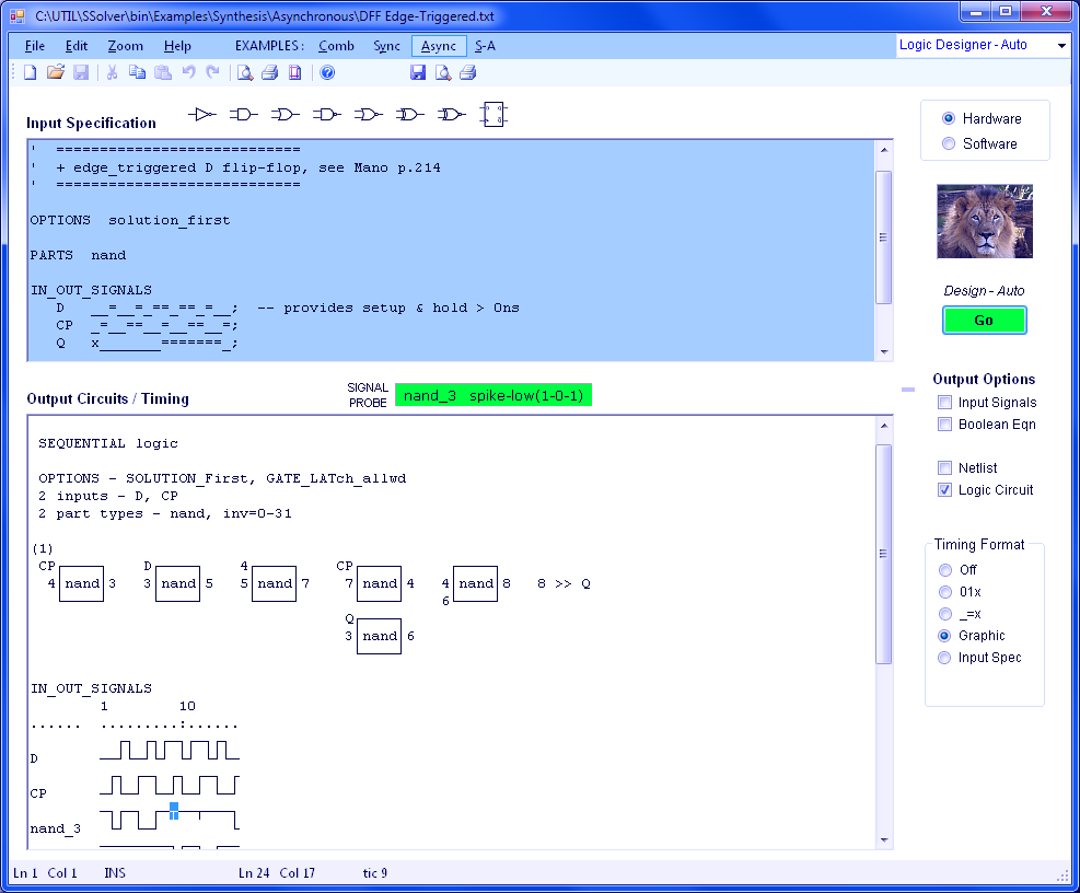
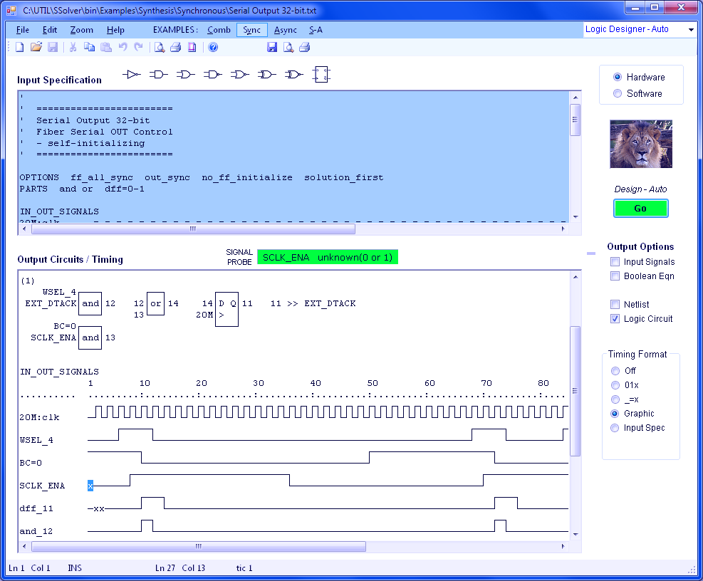
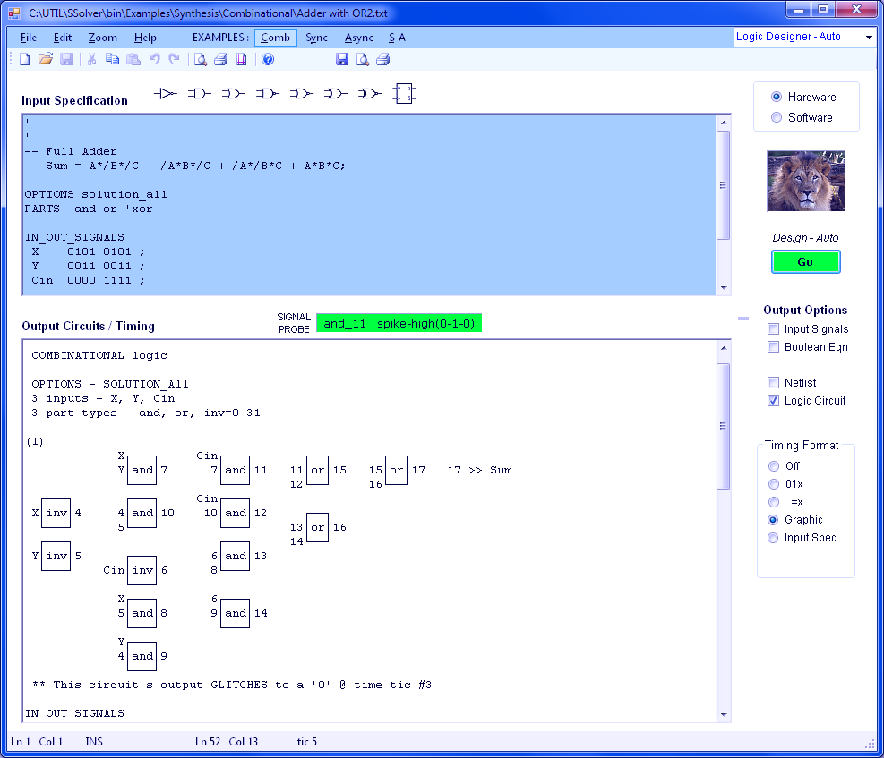
The free Logic Design Auto software automatically designs, minimizes and simulates small computer logic circuits. All types of digital logic are supported: Combinational - Sequential - Synchronous - Asynchronous.


User Guide
See Logic Design Auto Help for detailed documentation.
Design Minimization
The Logic Design software searches for digital circuits that provide the transfer function specified by the Input Window truth table, signal timing diagrams or waveforms. In general, the first circuit solution found will be the simplest solution possible. Refer to U.S. Patent 6253365 "Automated design system for digital circuits".
Input Specification Window
The input-output signal relationship of the logic circuit or state machine can be specified by a truth table or a timing diagram. Data can be edited, cut and pasted, or loaded from a file.
Logic Design features
Logic functions - inverter, and, or, nand, nor, xor, xnor logic gates and D flip-flops
Flip-flop state initialization
Spike/glitch detection
Logic states - 0 1 x r f (0, 1, don't care, rising, falling)
For detailed part descriptions, refer to Logic Parts Data
Output Window Options
Output Options are identical to the Logic Design Draw and Logic Simulation tools. The Output window can display any or all of the following: logic circuit input signals, Boolean equation, netlist, schematic drawing and timing waveforms.
