
|
8-Bit Programmable Computer |
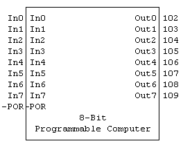
1. 8-Bit Computer Macro
The 8-bit Programmable Computer illustrates how a hierarchy of macro blocks can easily manage large designs using primitive, MSI and other macro parts.
|
8-Bit |
|
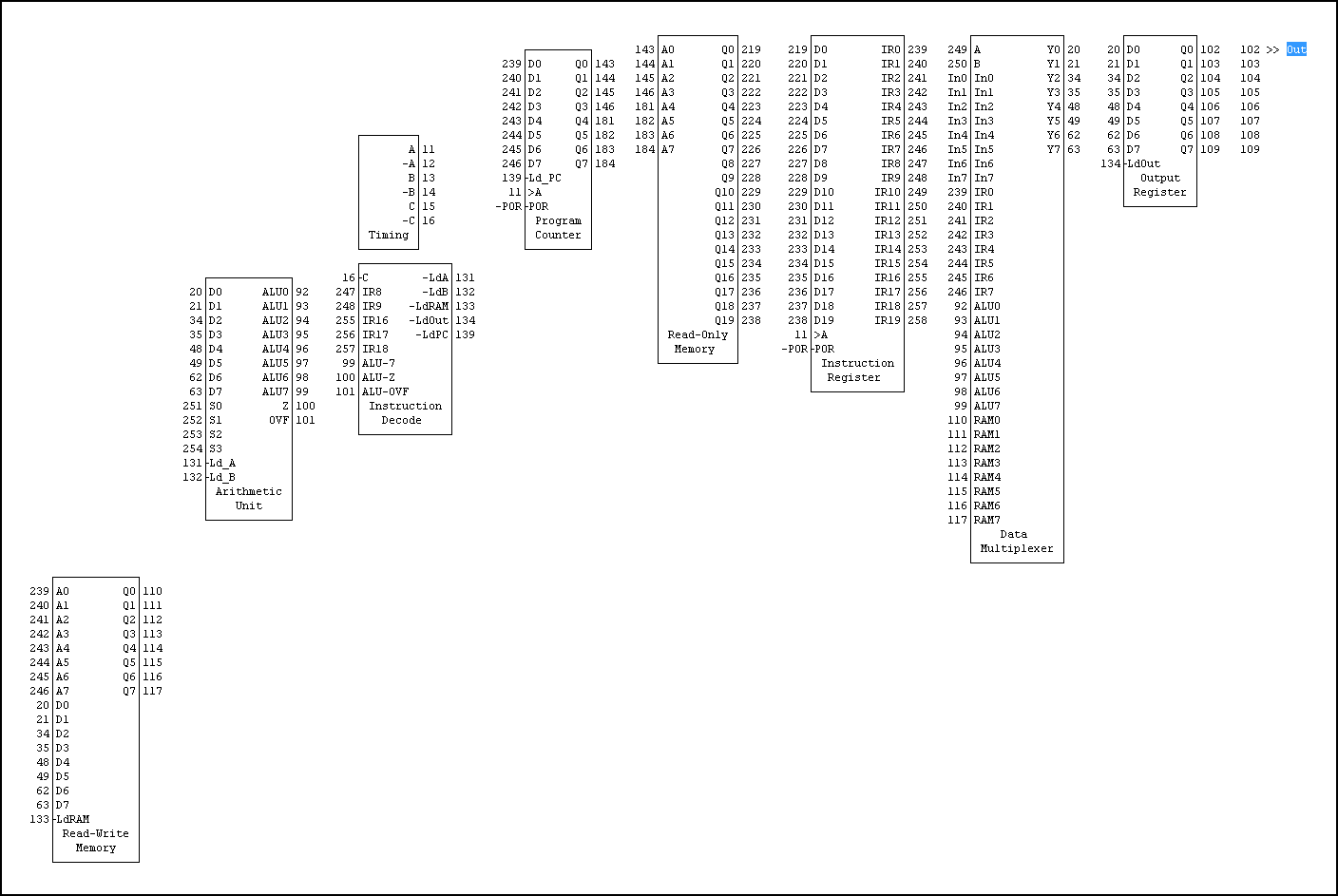
The 8-bit Computer macro was built from the 8-Bit Programmable Computer circuit, which in turn was built from nine other macros.
|
8-Bit |
|
A brief description of each of these nine macro blocks follows. Schematics of all macros are in the Logic Design Draw/Logic Simulator Examples: Computer "Macro Schematics" directory.
1. Timing
The Timing block contains an oscillator and a divide-by-5 Johnson counter. Six timing terms, A -A B -B C -C, are provided to sequence control logic. For the 8-bit Computer, only A and -C are used.
The operational sequence of each computer instruction is:
a. The Instruction Register latches the Read-Only Memory output and the Program Counter is incremented or loaded
b. The Instruction_Decode decodes the instruction bits to generate load signals for the Arithmetic_Unit, Read-Write_Memory, Output_Register and Program_Counter
c. The output of the Program Counter provides the Read-Only Memory address for the next instruction
d. The Read-Only Memory outputs the next 20-bit instruction
2. Program_Counter
The Program_Counter (PC) is an 8-bit counter which sequences up to 256 computer instructions in the Read-Only Memory. Normally the PC starts at a count of 0 and increments after each instruction is executed. For Branch/Jump instructions, the PC is loaded by the Branch address.
3. Read-Only Memory
The 256-word by 20-bit Read-Only Memory consists of (5) 256x4 ROM4 parts and contains the computer program. The data in these ROM4 parts must be defined before simulation. To change the program, the Read-Only Memory circuit must be edited and the macro must be rebuilt.
Currently there is only a 10-word program in the Read-Only Memory:
0 00000 nop
1 12405 A=5
2 13509 B=9
3 16B00 Out=A+B
4 17B00 Out=A-B
5 18B00 Out=A*B
6 18800 A=A*B
7 13502 B=2
8 19B00 Out=A/B
9 1EB00 Out=A Or B
4. Instruction_Register
For each instruction cycle, the Instruction_Register latches the instruction data from the Read-Only Memory.
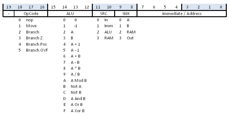
5. Instruction_Decode
The Instruction_Decode decodes the instruction bits to generate load signals for the Arithmetic_Unit, Read-Write_Memory, Output_Register and Program_Counter
The Instruction word format is shown in the following figure:
6. Data_Multiplexer
The Data_Multiplexer selects one of four 8-bit inputs and generates an 8-bit data output which can be used to load the Arithmetic_Unit, Read-Write_Memory, Output_Register and Program_Counter.
Data inputs to the multiplexer are In0-7 (Computer Input), IR0-7 (address field of the 20-bit instruction), ALU0-7 (Arithmetic Unit output), and RAM0-7 (output of the Read-Write Memory)
7. Read-Write_Memory
The Read-Write_Memory, which consists of two RAM4 parts, provides 256 8-bit words of read/write memory.
8. Arithmetic_Unit
The Arithmetic_Unit has two input registers (A, B) and an 8-bit Arithmetic-Logic Unit (ALU8).
The ALU8 part supports a total of sixteen signed-integer-arithmetic and bitwise-logical operations. It is similar to the 4-bit LS181 ALU, but ALU8 is an 8-bit part and additionally has multiply, divide and mod/remainder operators. It has two 8-bit inputs, A and B, and a 4-bit function select (S) input.
Refer to Logic Parts Data for a full description of ALU8.
9. Output_Register
The Output_Register provides the output of the Computer. It can be loaded under instruction control by any input to the Data Multiplexer.